Archive : Article / Volume 1, Issue 1
- Research Article | DOI:
- https://doi.org/10.58489/2836-5127/002
SMPTE in Radiology: The Forgotten Quality Control Test â A Pictorial Essay
Radiology Specialist, Radiology Department, Al-Namas General Hospital, Ministry of Health, Al-Namas City, Saudi Arabia.
Abdulwahab Alahmari
Abdulwahab Alahmari, (2022). SMPTE in Radiology: The Forgotten Quality Control Test â A Pictorial Essay. Journal of Radiology Research and Diagnostic Imaging. 1(1). DOI: 10.58489/2836-5127/002.
© 2022, Abdulwahab Alahmari, this is an open access article distributed under the Creative Commons Attribution License, which permits unrestricted use, distribution, and reproduction in any medium, provided the original work is properly cited.
- Received Date: 01-10-2022
- Accepted Date: 14-10-2022
- Published Date: 28-11-2022
Radiology; Quality Control; SMPTE Pattern; American College of Radiology; Accreditation.
Abstract
Introduction
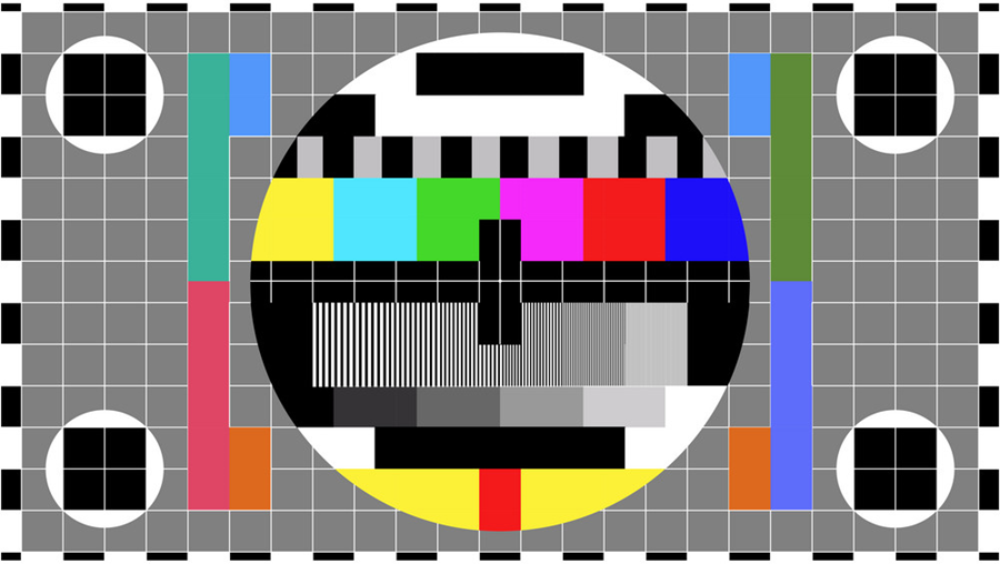
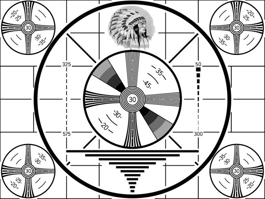
All of us saw those colored images on Television (TV) with buzzing sound and especially in old public TVs see (Figs. 1, 2, and 3). These screens are called SMPTE screen which are used to tone the image and the sound for the people watching the TV before the TV shows started. There are three designs of TV SMPTE, the new ones are presented in see (Fig. 1 and 2) and the older one is presented in see (Fig. 3). The letters SMPTE stands for the Society of Motion Picture and Television Engineers. However, SMPTE is used in radiology, not only in TVs. SMPTE is used as a quality control (QC) test for monitor display to tests its performance for The American College of Radiology (ACR) accreditation process. It is a standard test for screen QC program in hospitals which mean it must be done by specialized personnel, not like quality assurance (QA) where anyone can do it and be proactive. This paper will focus on image quality of monitors in radiology departments by testing those monitors by using the SMPTE pattern.
Image display monitor is the weakest link in the digital imaging chain. The displayed image quality might affect the radiologist decision in reporting the examination. Not all computers have high quality monitors that can be used to interpret medical images due to the cost of monitors used in radiology workstations. The radiologist’s workstation monitors have the highest quality, usually 2K-3K for radiographs and computed tomography, and even up to 4K for mammogram images. Megapixel measurements can differentiate which monitor can be used in medical imaging and which can’t be used. Meanwhile, commercial monitors have 1K resolution. Therefore; the quality of the image on radiology monitors and printers must be maintain at the highest level of quality using the SMPTE pattern test.
History
In 1939, they used in most TVs in the United States the “Indian-head” image pattern which was introduced by Radio Corporation of America (RCA) see (Fig. 4). In 1951, the Society of Motion Picture and Television Engineers formed a committee of clinical radiology departments, representatives of the industry, and the SMPTE society representatives. Many versions of patterns were introduced and tested. In 1985, a recommendation practice was published by the Society of Motion Picture and Television Engineers (PR-133) [1]. This recommendation entitled “specification for medical diagnostic imaging test patterns for TV monitors and hard-copy cameras”. This practice guide introduced the SMPTE as monochrome test pattern to be the quality control test of hard-copy films, videos, and image display systems. The monochrome test has higher resolution than the color display because the color display has a ½ of the monochrome test resolution. Therefore; the monochrome image is used, not the color bars. Even thou, some companies made colored SMPTE that is close in resolution to the monochrome SMPTE. Before SMPTE used, the output including amplifier, analogue-to-digital converter, film (a hard-copy), and displays were not tested [2].
Concept
The recommendation practice of SMPTE sets specifications and attributes for the SMPTE pattern. This SMPTE pattern is sold by medical devices industries and medical equipment vendors. This SMPTE is introduced to test image display systems and films printer.
Designs and Parts of the SMPTE
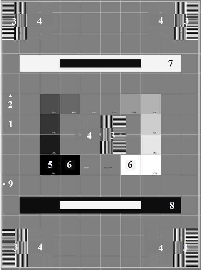
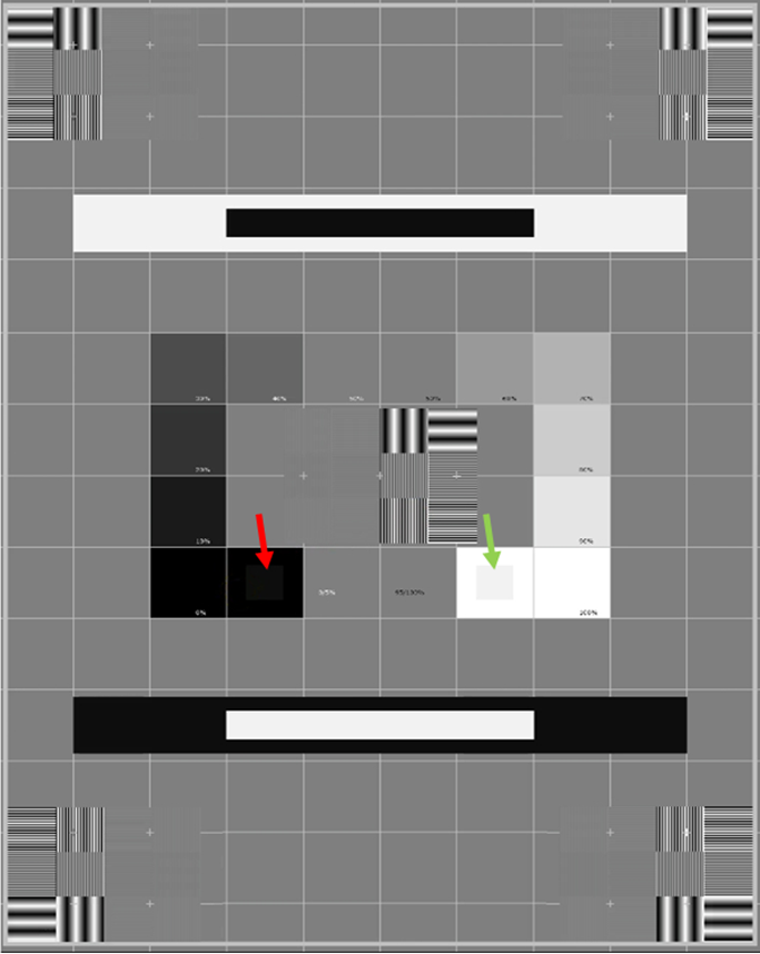
Here are the parts of the patterns: 1) the uniform grey at the 50% level which allows to detect uniformity issues or artifacts in the image, 2) A cross-hatched pattern which is set at 75% of maximum level of the picture to determine the spatial distortion effect to determine whether the whole picture is on the film?, 3) the low contrast resolution on the film in all four corners and the low contrast resolution ranging from 1% to 5%, 4) the high contrast resolution on the film in all four corners and the high contrast resolution patterns which all at the level of 100%, 5) a grey scale pattern placed in the center of the SMPTE to avoid the light associated with recording system or image display, or output falling-off. This grey scale is the 12 boxes with 10% increment from 0 to 100%, except the box 50% is duplicated, 6) the 5% incremental patch at the end of each path placed in the big boxes of the 0-5% box and inside the 95-100% box see (Figs. 5 and 6) (i.e., the green arrow and the red arrow respectively). These boxes from 0-100% test whether the range of data is displayed correctly and it allows calibrate the brightness and the contrast controls, 7) a white window with black box in which test the system transition (from black to white) and low frequencies responses, 8) a black window with a white box in which test the system transition (from white to black) and low frequencies responses. Both 7 and 8 windows must show a clean transition without any smearing, overshooting, or ringing, 9) the border which is set at 75% of maximum level of the picture to determine the spatial distortion effect to determine whether the whole picture is on the film? All these number are illustrated on the SMPTE pattern see (Fig. 5). The Spatial resolution is demonstrated with the linearity of the lines. Any aliasing or distortion indicate poor image quality. It is within acceptable limits if contrast bars white and black are distinct from each other.
Performing the Test
A-Display Monitor
Software like MediCal QAWeb have all required patterns by the ACR. There are two important boxes in the SMPTE pattern, the 0- 5 % box (the red arrow) and the 95-100% box (the green arrow) see (Fig. 6). If the evaluator of the screen/monitor sees these two boxes then the screen passes the test. It is like checking if the old viewing boxes’ lights are working and the intensity of the light can be manipulated until the X-ray or CT scan films are clear on the viewing box.
The SMPTE is used to adjust the contrast and brightness of a video display like CT and MRI or a video monitors like US and fluoroscopy. The signal of voltage peak coming from an image is different than the signal of voltage peak coming from a video. In order to show a video correctly, turn off the contrast and brightness control then turn it on until the raster pattern is barely visible. Then adjust the control of the contrast until the 95% patch is clearly seen without smearing or tearing of the alphanumeric or the pattern. So, the brightness first is done followed by the contrast. The room lighting must be adjusted to prevent any reflection of the light on the screen. The image display is similar, but the appropriate window width and level must be selected.
B-Films Printer
The 0% patch is set to produce 2.45 density on a laser hard-copy recorder; even though; higher densities can be printed on the film. But if higher densities are used, it will make the 5% patch disappear, the diagnostic information on the film will disappear too, and the film will look different than the visual display (the monitor). The use of a photometer to adjust the contrast and brightness to have the same luminance on all displays theoretically, but it will not work. The fact that all display has different light output colors; even though; they all have the same phosphor amount and type in all of them which will result in a quantitative mismatch.
To perform the SMPTE test on a film printer, send the SMPTE pattern to the film laser printer as 1 picture on 1 film or 4 pictures on 1 film format which are the most commonly used format in radiology film printing. If the film needs processing, then the processing must be done (only if applicable). Place the film on the viewing box after adjusting the light of the box and the light of the room appropriately. Then compare the image on the film to the image on the monitor (the monitor must have been tested). As well, compare the film gray scale densities to monitor gray scale densities. If an object is whiter or darker on the screen than the film, then the printer needs to be fixed (if possible) or replaced.



The Effect on Hard-Copy
Printed films and compact discs (CDs) are both hard copies of the image display. These are some effects that might be spotted on a hard-copy: burn of the cathode ray tube (CRT) phosphor, effect of a raster erase feature, the effect of two raster erasing features one from the video hard-copy recorder and one from the image source working simultaneously, excessive CRT phosphor grain, and smearing or tearing of the image of the high-density portions. The SMPTE is helpful in detecting the source of the problem in the laser hard-copy recorder’s timing issues and smoothing algorithms. Eventually, it is possible to produce a film that looks like the displayed image on the monitor.
Look-Up Table
Look-Up Table (LUT) controls the luminescence and brightness of an image. LUT is made of binary numbers that use mathematical equations in post-processing stage to reference histogram, create accurate mapping function, and reassign grey scale image into different values that makes a new image. Many confuse luminescence with fluorescence. The difference between luminescence and fluorescence is that photon is emitted without heat/atom excitation and with heat/atom excitation respectively. The LUT controls the luminescence by assigning for an input value an output value. The LUT will calculate the values very quickly. The pixel value for a grey scale and black and white picture is from 0-255. In black and white image, the value of 0 represent very dark black and the value 255 represent the lightest white. For example; an 8-bit image done using the LUT which will take all values from 0-127 (which are grey scale pixels) and turn them into white and take the values of 128-255 (the darker shade pixels) and make them black see (Fig. 7). In radiology, if a radiograph is too white or too dark the computer will look into the LUT to adjust the image to look better. Some information in the radiograph can be lost and never be retrieved in the post-processing due to the use of LUT. As well, artifact can be present due to the post-processing using the LUT. Unsharp masking is an example of using the LUT which makes a copy, blur the image, and subtract it from the original image. Bone edges are not clear on the blurred image, but the subtracted image will make bone edges appear clearly. The rest of the image will be adjusted until pixel values become closer to each other.
The LUT will change the image/gamma contrast, brightness alteration, grey value spreading, and setting individual gradation curves. The LUT will not increase the work load on the Central Processing Unit (CPU) of the computer. In order to get a good image quality, the image with a bit depth of 10 bits per pixel is being processed, if the bit-depth of the imaging machine is greater than the LUT, the LUT output will have an interpolated linearly. As well the monochrome images will not be able to apply false-color LUT. In addition, it is not able to define separate LUT characteristic for each Red, Blue, and Green (RBG) color. Even thou, there are many software developers came over this issue by allowing giving colors to a monochrome image and for LUT images by assigning different LUT for each RBG color [3]. In image acquisition computers used in radiology departments, the look-up table used to correct nonlinearity in the hard copy recorders. If the system does not use a look-up table, then the printed film and display image on the monitor will look different. New techniques now make the colored display test has the same spatial resolution of the monochrome test. The lack of convergence and the issue of maintaining the purity of colors on a color display system as when the surrounding of the MRI field is exceeding 0.5 gauss. Another issue with color display is the low dynamic range compared to monochrome image, because the color image will have the three colors RBG making a one pixel. Which makes the output of the colored pixel 1/3 of the spatial resolution of a monochrome image. As well, the shadow mask that is used in color display to separate the phosphor will reduce the spatial resolution of colored image into 2/3 of the monochrome. Which as well will make the luminescence of the colored display 20-25% of the monochrome display similar to the contrast.
Color Display
Any typical monochrome display has a bandwidth of 15 MHz at minimum. A regular video display −Television (TV)− has a typical bandwidth of 3.5 MHz. The monochrome phosphor is a continuous layer coating, while the color phosphor is made by different elements of red, blue, and green, divided by a shadow mask. Therefore; a monochrome pattern is used in radiology, not a color pattern.
Conclusion
The SMPTE pattern is useful to test monochrome and colored display of film printers and monitors. It provides quantitative and qualitative assessment of any reduction in contrast, resolution, and dynamic range of monochrome or color images on monitors or films.
References
- RP133, S. M. P. T. E. (1991), Specifications for Medical Diagnostic Imaging Test Pattern for Television Monitors and Hardcopy Recording Cameras. Society of Motion Picture & Television Engineers (SMPTE) ;595
- Gray, J. E. (1992), Use of the SMPTE test pattern in picture archiving and communication systems. Journal of Digital Imaging. 5(1):54-58
- Alahmari A. (2022), Coloring CT Scan Images. O J Radio Med Img. 5(1):10-12

